OTR MINE TIRE CUTTING MACHINE
DEVELOPING A MOVEABLE OTR MINE TIRE CUTTING MACHINE
End user:
Mines with different types of vehicles equipped with large tires.
Over the years, there has been an accumulation of large tires that are difficult to dispose of due to the lack of a system able to reduce and separate the materials of which the tires are made. Currently, there are systems able to deal with ordinary tires, but their use is not economical for large tires.
Software:
AUTODESK INVENTOR used for the preliminary study;
CREO PARAMETRIC used for achieving the executive design and the construction drawings.
Project:
To develop a moveable system for cutting OTR mine tires that measure between 49” and 63”
The challenge:
the system must be able to deal with very large and heavy tires of different sizes from about 4000×1500 mm (O.D. x Width) of a 59/80R63 tire (weight about 5,5 tons) to 2400×600 mm (O.D. x Width) of a 21.00-49 tire (weight about 2.000 kg); the diameter of the rim ranges from 1600 to 1245 mm.
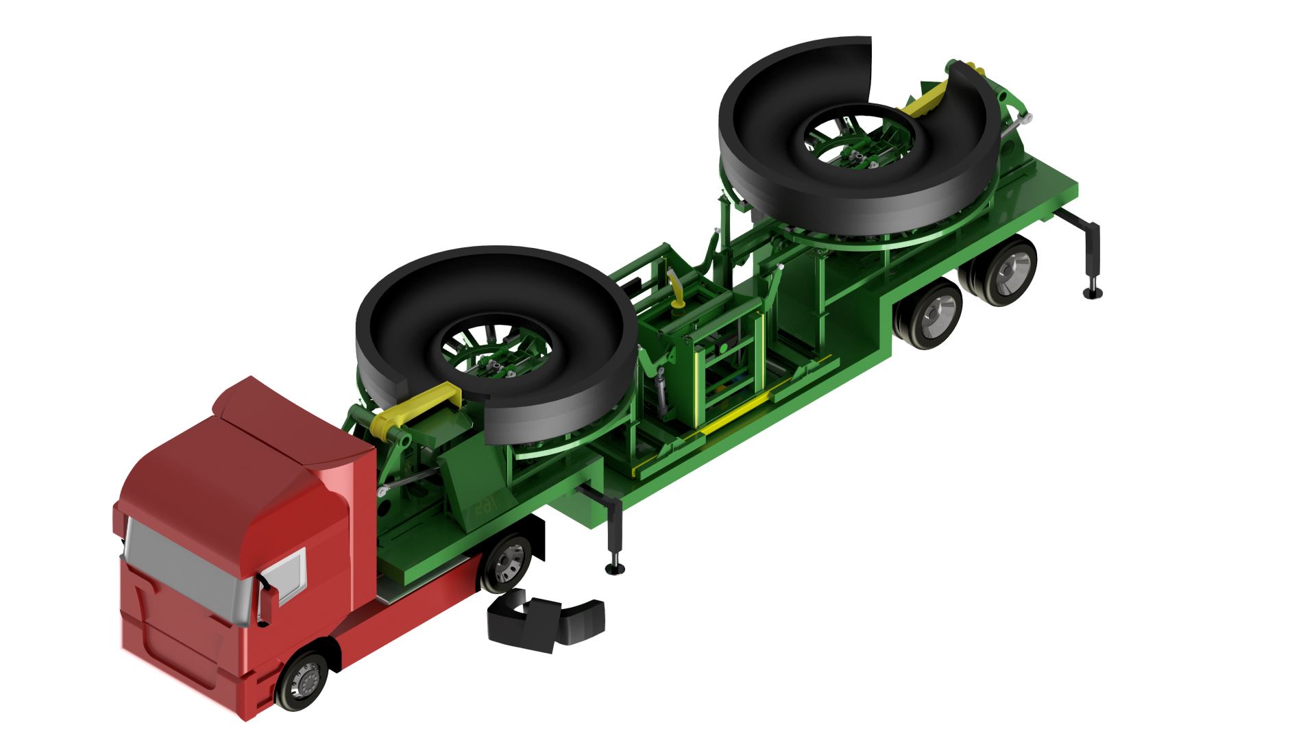
The system must cut the tire in two parts vertically, move each part horizontally and then slice each part in slices at a maximum weight of 100 kg each. Moreover, the machine’s size must comply with the max dimensions of a European standard trailer (i.e. 2,550x4x12 m WxHxL). The whole duration of a complete cycle for a 63” tire must be less than 20 minutes. The weight of the empty structure shall be a max of 13 tons.
Preliminary study:
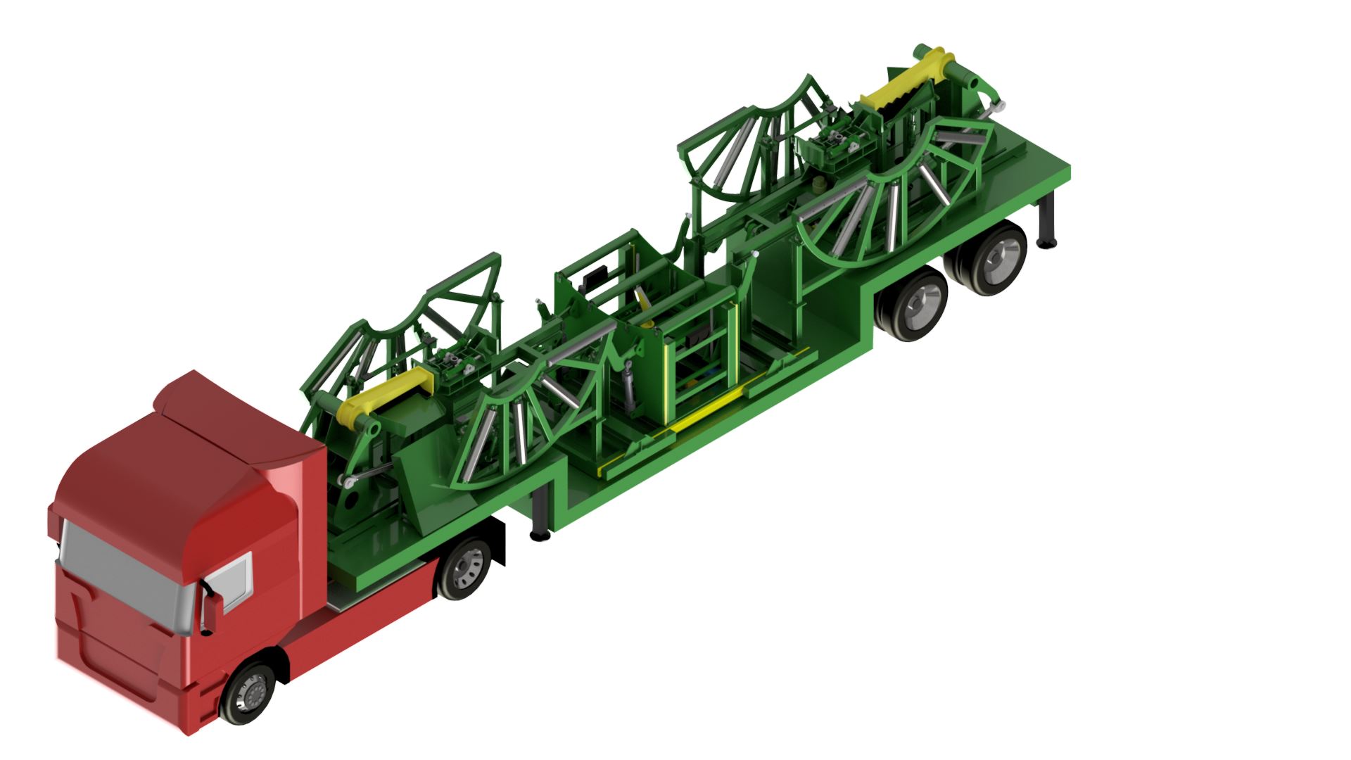
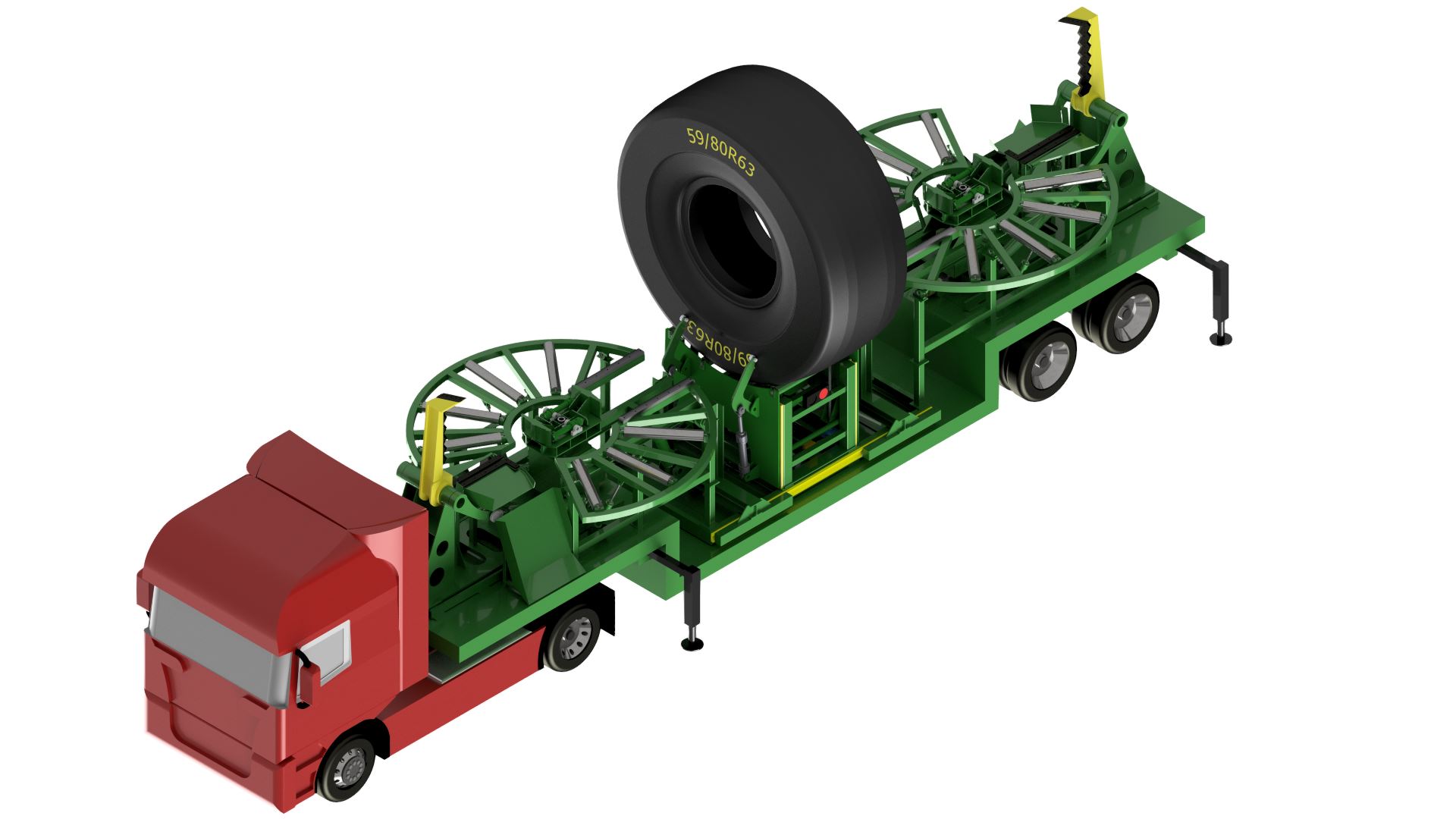
The preliminary study illustrates the basic principles of the idea that is a system mounted on a trailer with a central area where the tire is positioned and cut in half.
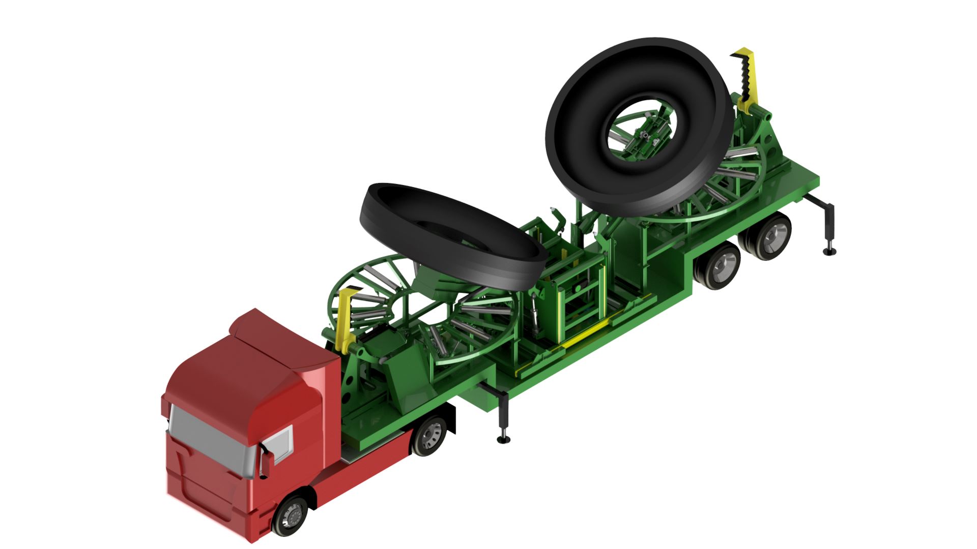
Two rotating “towers” place each half on two horizontal shelves where they are sliced by two blades positioned at the ends of the trailer.
Our intervention:
Starting from the preliminary study, we have first identified the critical points of it. One problem is the locking and moving system of the tire during the transition from the vertical position to the horizontal position. Our solution includes the self-centering of the rim’s ring by means of the hydraulic cylinders. Subsequently, a shaft mounted on the bearings makes the whole group rotate with the tire attached. The central part where the tire is positioned vertically is equipped with a blade that rises and cuts the tire in two parts.
The structure that keeps the tire in horizontal position can be closed to meet the standard dimensions of the trailer. This was achieved by dividing the structure in two parts, a horizontal and a vertical part, joined by pins. A cylinder opens and closes the horizontal part.
The knife for slicing the tire is mounted on a structure that can be adjusted horizontally and is able to fit the different sizes of the tires; the shape and the materials of the knife equipped with a series of special blades have been thoroughly studied to be able to cut the steel cables embedded in the tire rubber. Finally, a chute allows the cut pieces to slide out of the trailer.
The result:
We were able to meet all of the specific requirements, with the exception of the weight of the empty structure. The weight of the whole machine, trailer included, respects anyway the limits of the road transportation. However, we have considered that this requirement was the least limiting since a 4 axle semi-trailer can bear up to 40 tons. The maximum duration of the cycle was reduced to 18 minutes.
The next challenge:
to deal with the execution phase of the products by selecting suppliers and coordinating their activities, issues and deliveries.


